My Own ESP01 Home Assistant Project
In this post, I’ll walk you through how I created my own smart home ecosystem using the tiny ESP-01 module, the powerful ESPHome framework, and some good old-fashioned soldering. I designed and built custom-perforated plaque (perfboard) circuits to control everything from RGB mood lighting to my main ceiling lamps.
Note: I assume you have some knowledge about electronics, programming and you have already set up home assistant and esphome. If you are new then start from there: Home Assistant Installation - ESPHome for Home Assistant
Why Build It Yourself?
- Cost-Effective: An ESP-01 module costs next to nothing. Combined with a few basic electronic components, you can create a smart device for a fraction of the price of a commercial one.
- Ultimate Control: No reliance on third-party applications or subscriptions. Everything runs locally within my Home Assistant instance. My data stays in my home.
- Flexibility: ESPHome allows for incredible customization. I can define exactly how each button, relay, and sensor behaves directly in a simple YAML configuration file.
⚠️ A Very Important Safety Warning: Working with 220V (or any mains voltage) is extremely dangerous and can be lethal. If you are not 100% confident in your knowledge of electrical safety, please do not attempt to replicate the high-voltage parts of this project. Always disconnect the power at the circuit breaker before working on mains wiring. Ensure proper insulation and separation between high and low-voltage components.
Challenges and Solutions
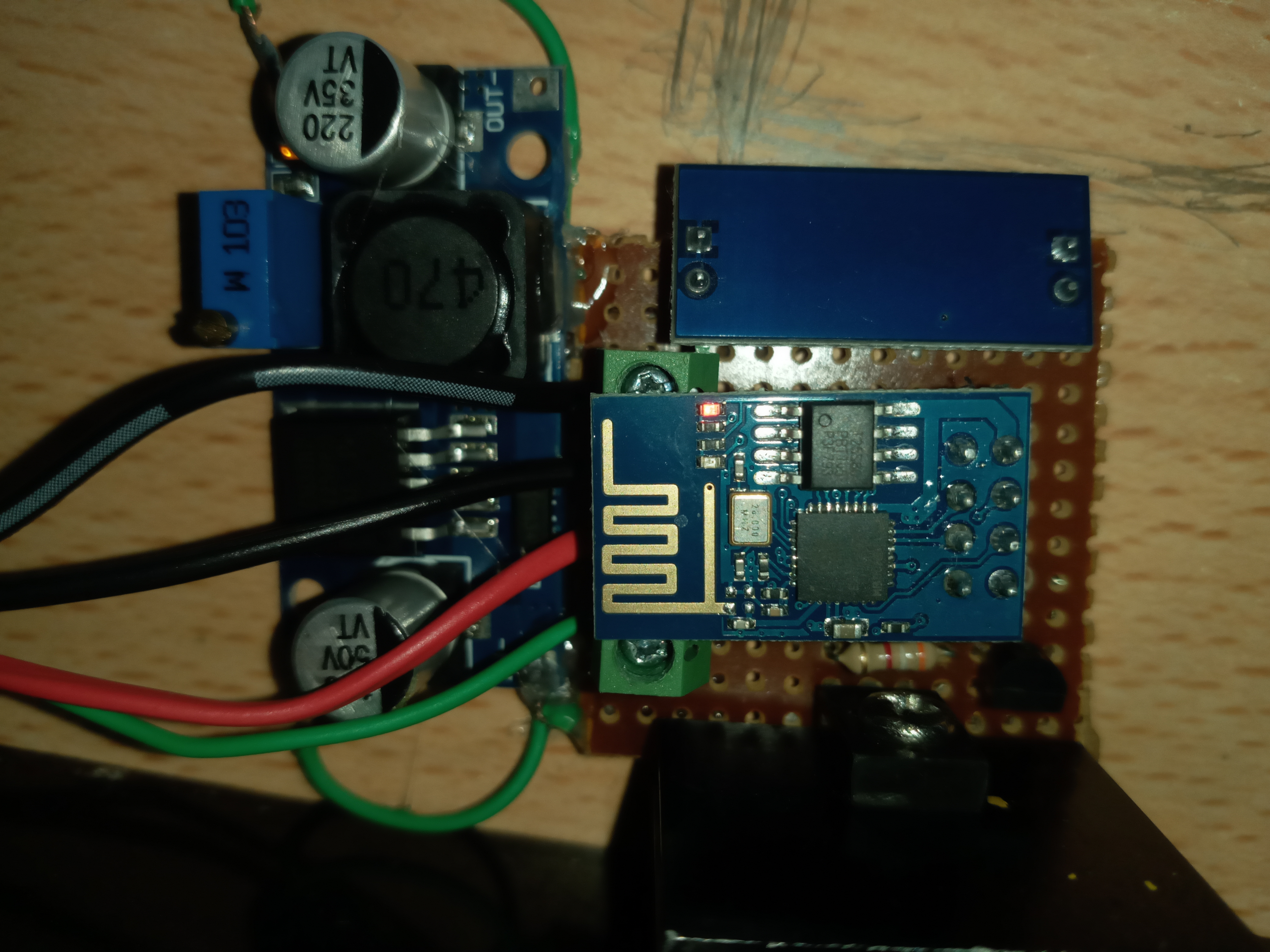
A Critical Detail: The Power Supply Solution
My first thought was to use one of the many cheap, compact “AC-DC 220V to 5V” modules you can find online. However, after some research, I became concerned about their safety and reliability. These generic modules often lack proper electrical isolation, have poor voltage regulation, and may not have gone through any rigorous safety certification, posing a potential fire or electrical shock hazard. I wasn’t willing to risk that inside my walls and resulting in house fire.
- Cheap Tricky AC-DC 220V to 5V Converter Circuit
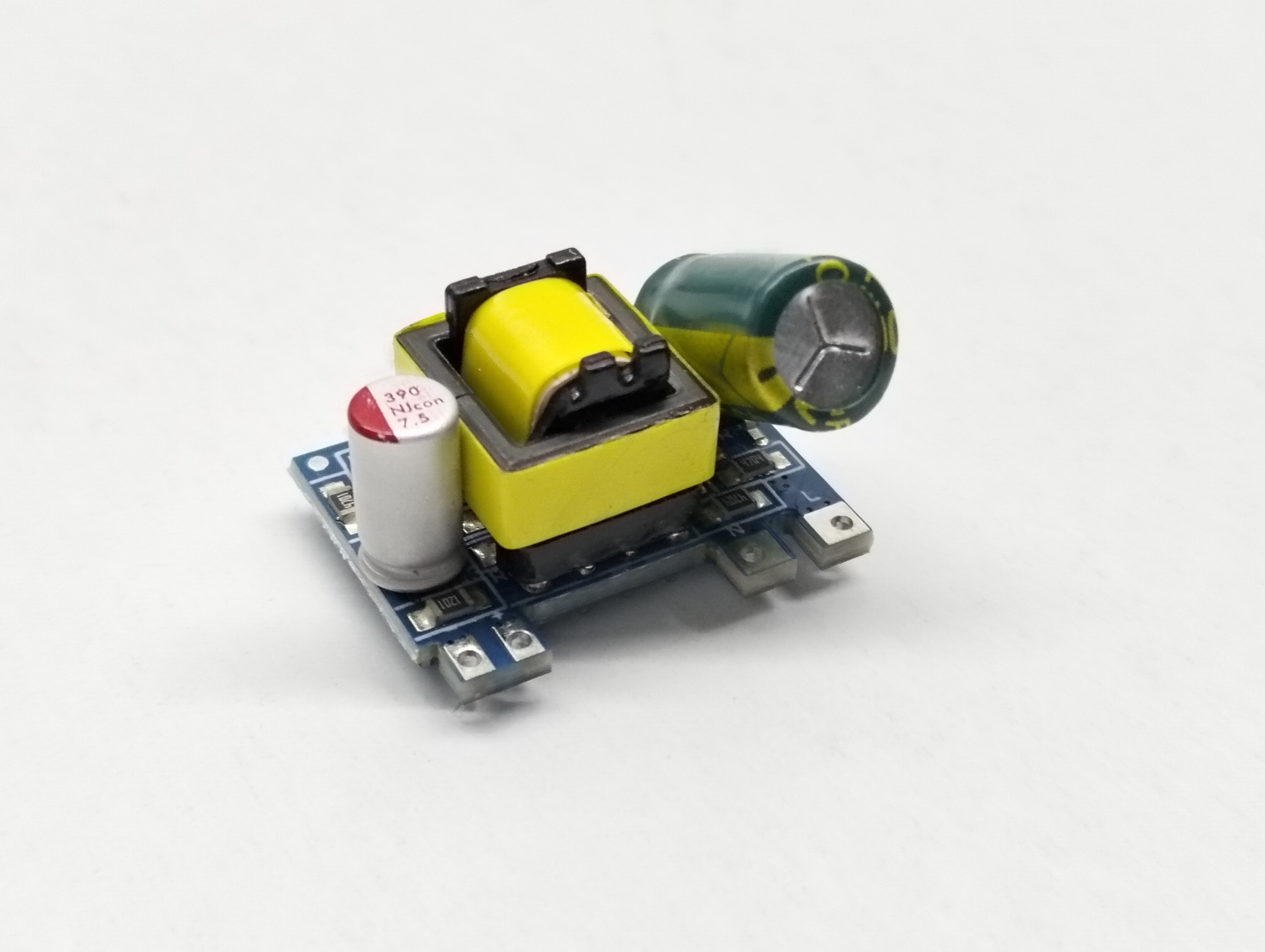
My solution was to harvest the power supply circuit from a high-quality, certified USB phone charger.
Major companies like Samsung, Anker, Huawei and AcBel spend enormous resources on engineering and safety. Their adapters are designed to meet strict international standards like CE, providing features like over-current protection, thermal shutdown, and proper mains isolation. By using the core of one of these, I’m essentially integrating a professionally engineered power supply into my DIY project. Even tough I am paying more money than I first anticipated but it is better than sorry.
- Example 12V 2A Adapter from AcBel Polytech

- The Process:
Select a Donor: I chose a genuine adapter. It’s important to use one with enough amperage to comfortably power the ESP-01, the relay, and any other components like 12V LED strips.
The Teardown: I carefully opened the adapter’s plastic case. This was the trickiest part, as they are often glued or ultrasonically welded shut. I used scissors which I used to cut the corners of adapter.
Integration: Once extracted, I had a compact PCB with clearly marked AC inputs and 5V DC outputs. I soldered my 220V mains wires directly to the AC input pads and used heat shrink tubing on all connections for insulation. This tiny board was then placed inside my project enclosure, well-separated from the low-voltage components.
Final Voltage Regulation: This “harvested” board provided a very stable 5V or 12V DC. I used this 5V line to power the relay module directly. For the ESP-01, which requires 3.3V, I added a simple and reliable AMS1117-3.3 voltage regulator that steps the 5V down to a clean 3.3V. If I need to power LEDs, then I used 12V DC adapter. I used another buck module to step down 12V to 5V for relay and I used AMS1117-3.3 to power ESP-01.
- Note: If there is an outlet in the wall then I don’t have to do those steps.
Devices
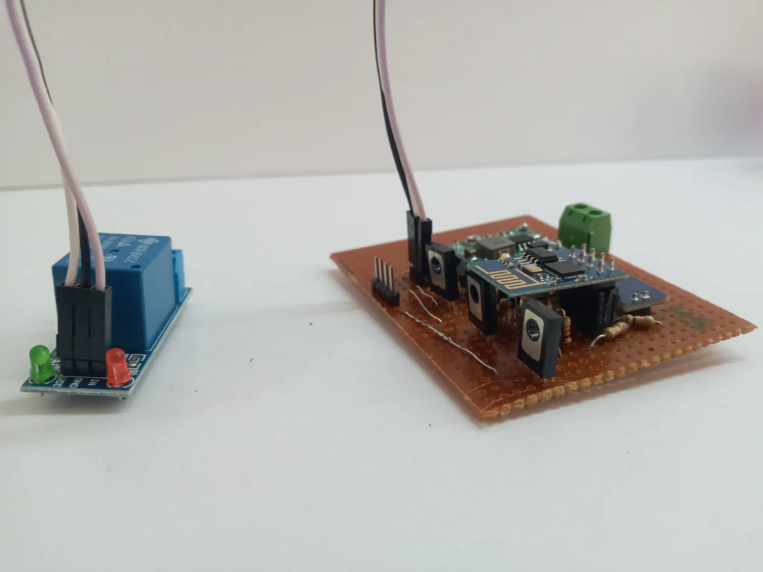
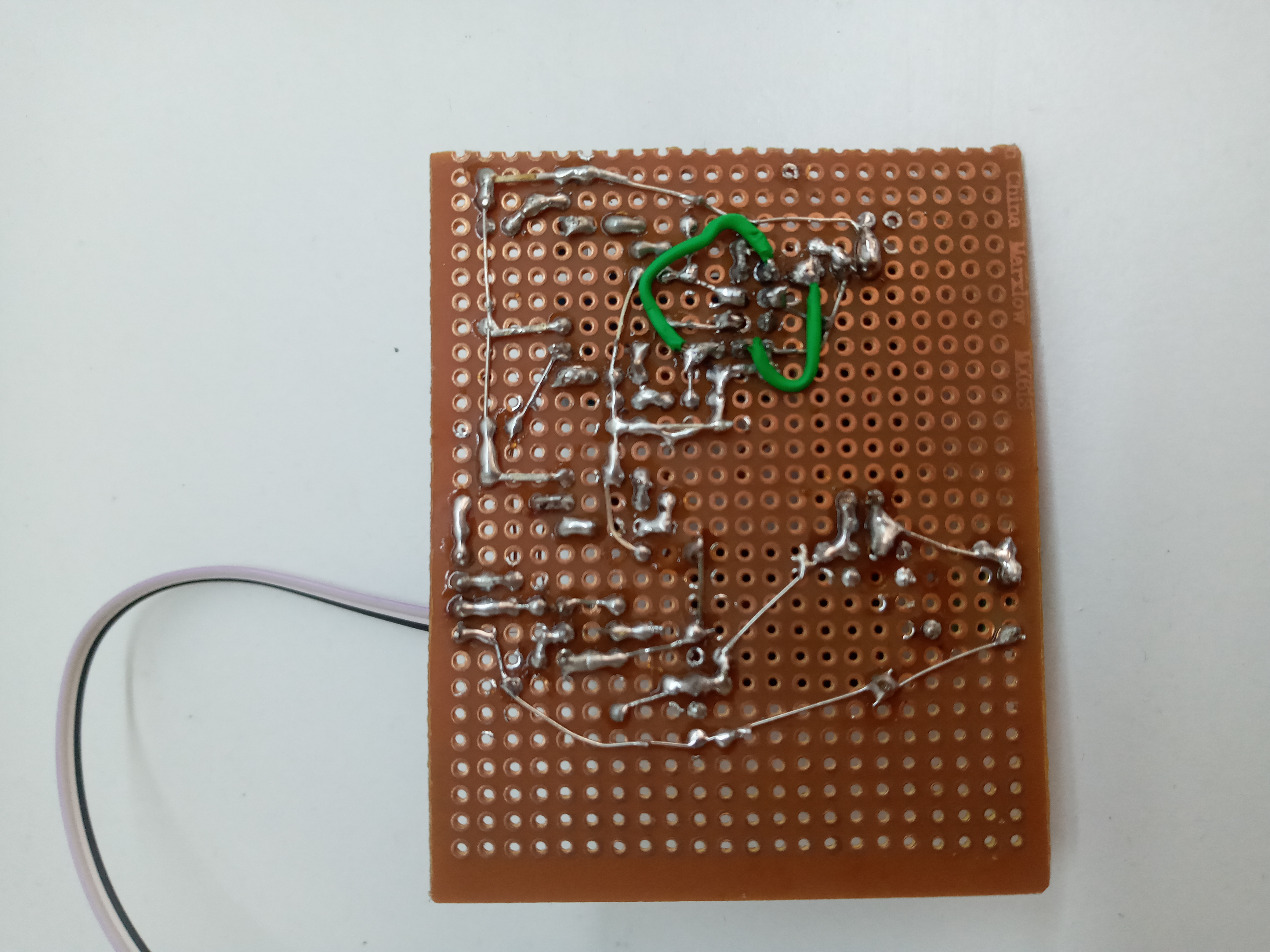
The core of this circuit is a 3.3V power supply for the ESP-01. One of the ESP’s GPIO pins is connected to the relay’s signal pin to switch the 220V socket on and off. Another 3 GPIO pins is dedicated to controlling the RGB LED lights. I used PNP and NPN transistors together for one channel of RGB LEDs. This is because ESP-01 chip wouldn’t boot up properly with only NPN transsitor it needs extra PNP transistor.
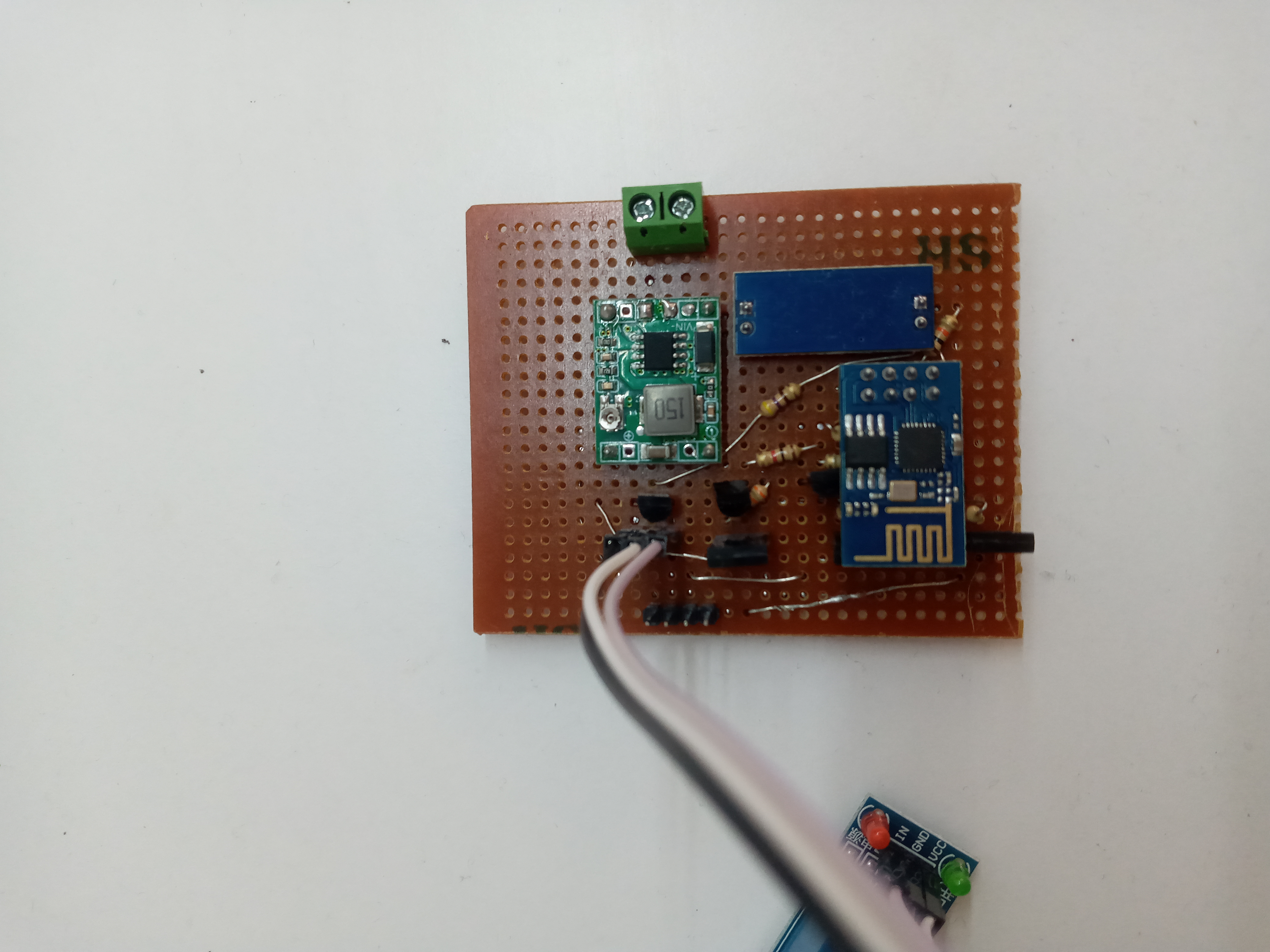
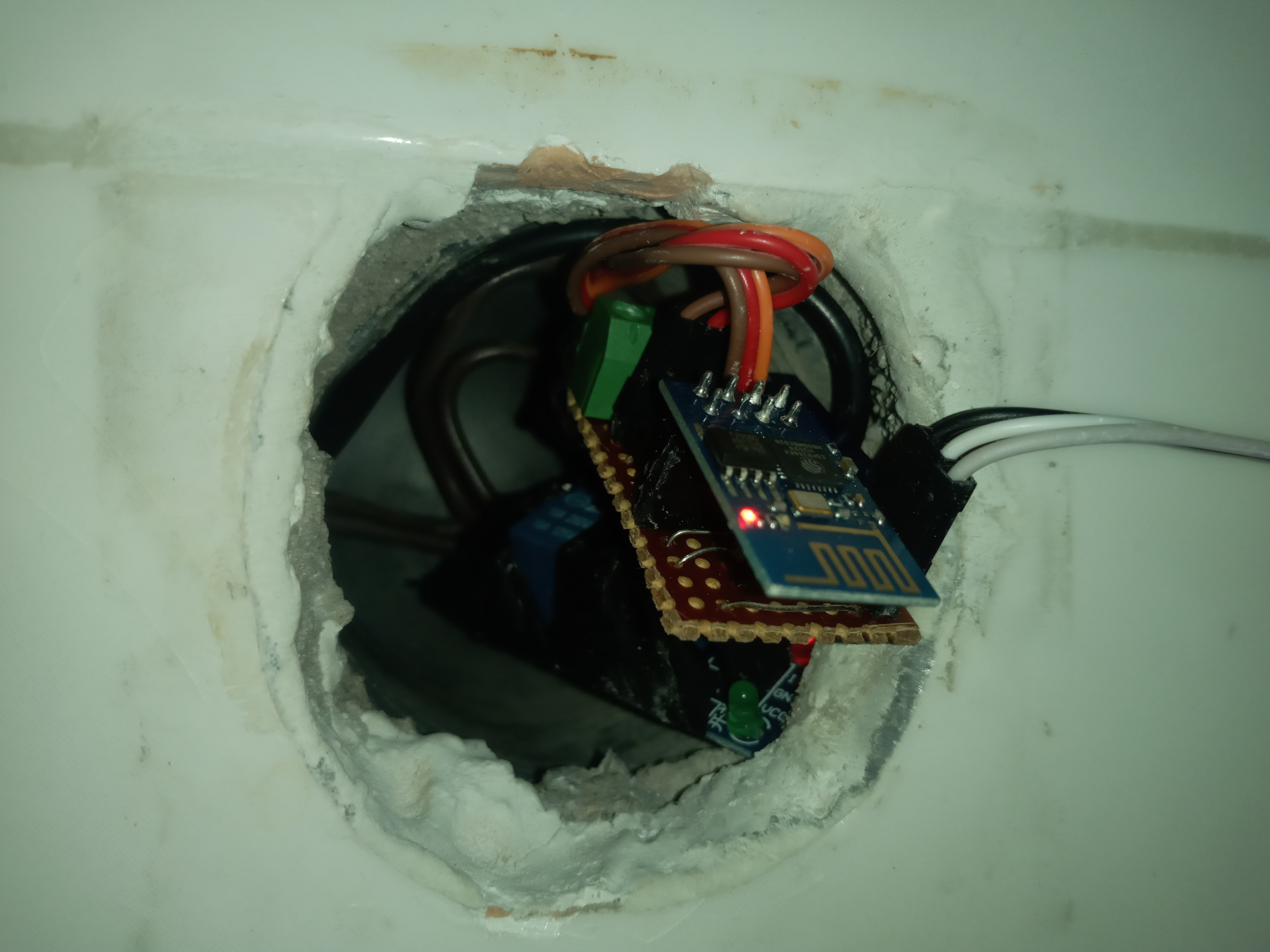
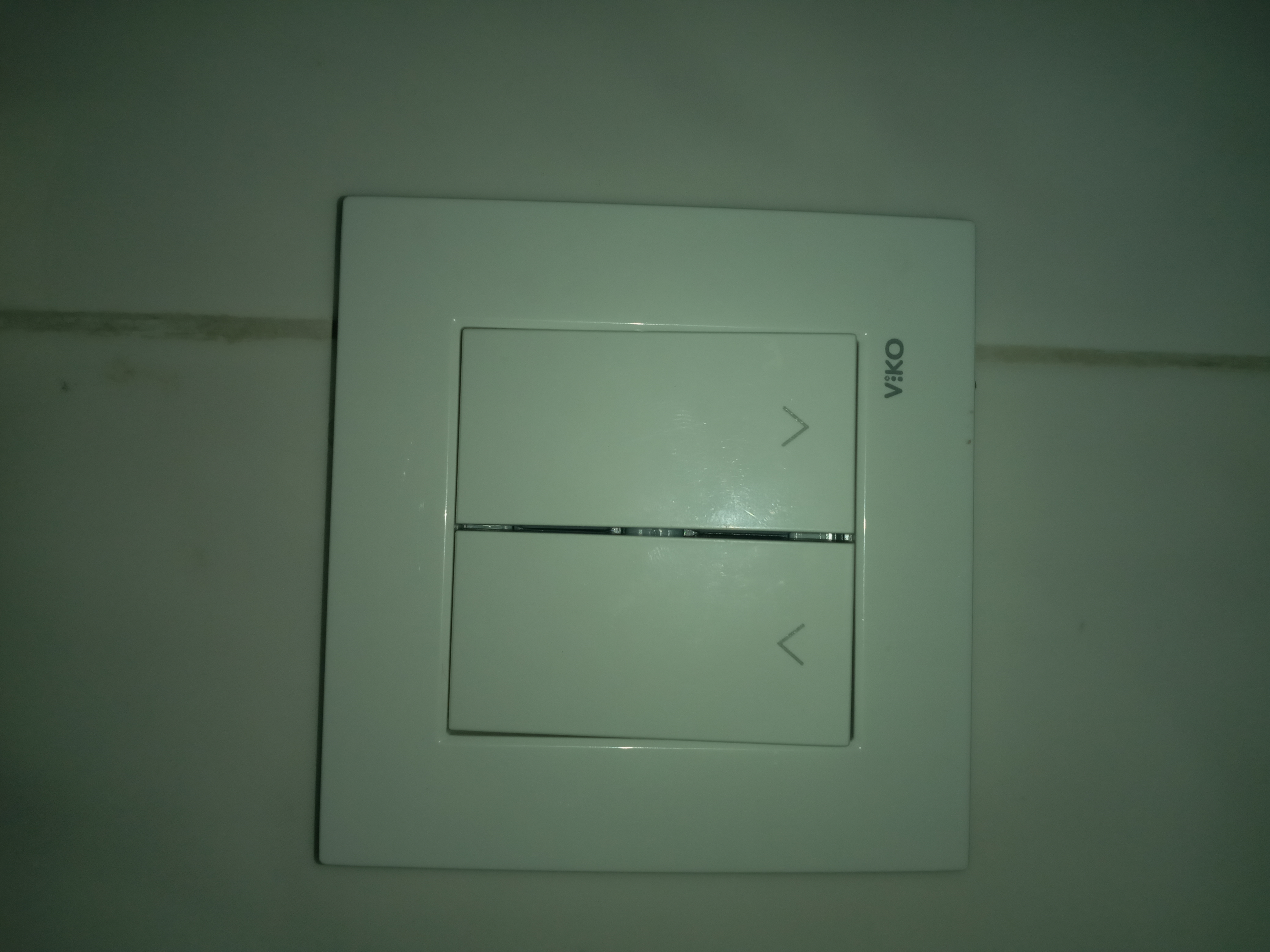
For wall switches and ceiling lamps, I used push button switch from local electrical supplies store. Even tough it is for 220V applications, I used it for 3.3V detection for ESP-01. Also I connected ceiling lamp through relay to ESP-01. Also I have to make the circuit very small to put in into wall hole.
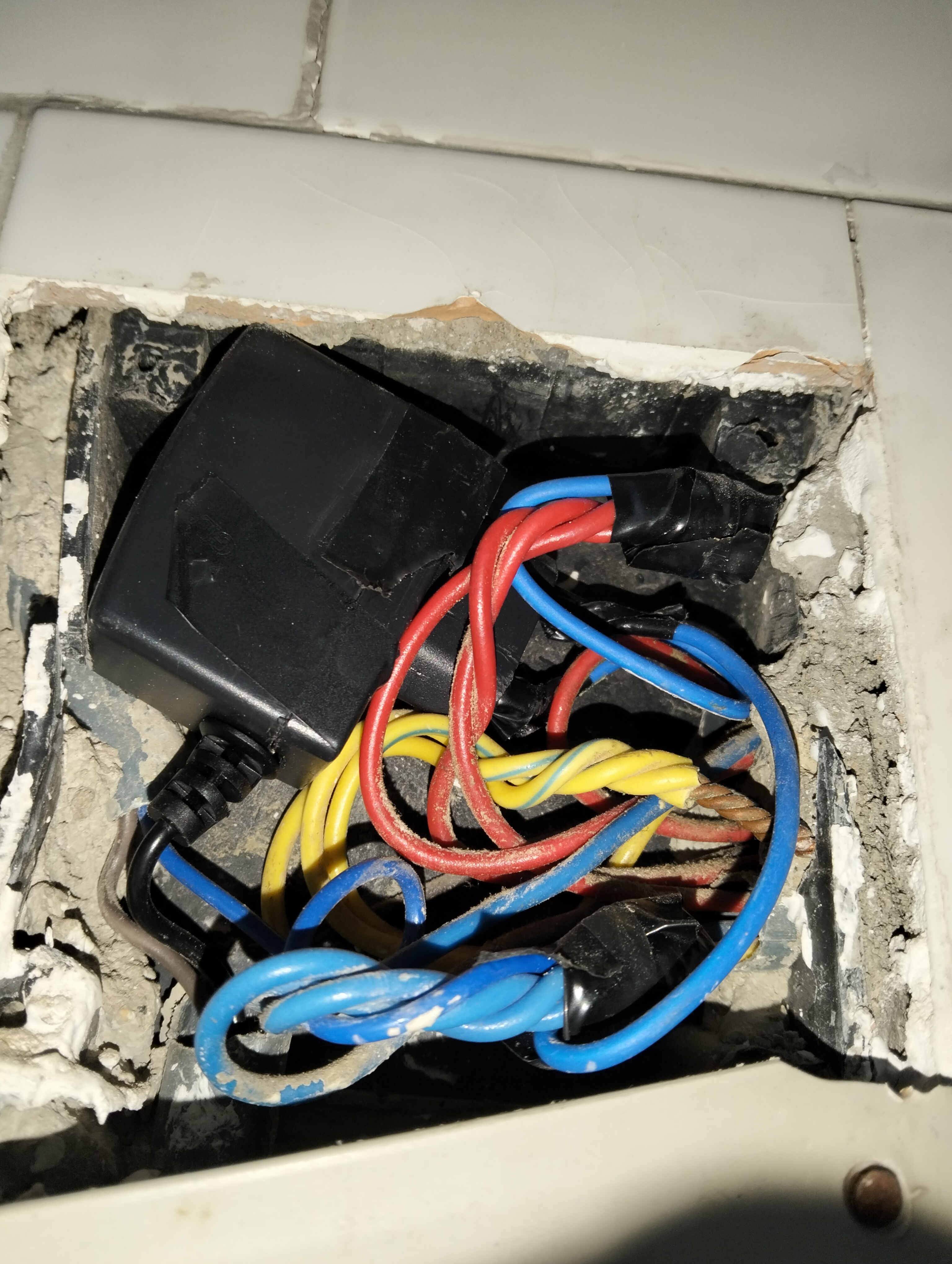
There was an outlet near to LED where I want to mount. So I used it as my power source without modifying adapter.
ESPHome Configuration
I first used basis code for all ESP-01 modules.
Same Basis Code for All ESP-01
esphome:
  name: esphome-web-134c1d
  friendly_name: ESPHome Kitchen Light
  min_version: 2024.11.0
  name_add_mac_suffix: false

esp8266:
  board: esp01_1m

# Enable logging
logger:

# Enable Home Assistant API
api:

# Allow Over-The-Air updates
ota:
- platform: esphome

wifi:
  ssid: !secret wifi_ssid
  password: !secret wifi_password
Then I used my own custom codes to adapt entities for Home Assistant. I planned and wrote these codes so that I can use the home assistant automation system. You can add as many entities as you want for one microcontroller.
ESPHome Kitchen Light - LED Lamp with Brightness Buttons Code
Summary: This adds brightness controllable LED light to the iterface of Home Assistant. With custom buttons, you can automate it with physical switch.
output:
  - platform: esp8266_pwm
    id: out_id
    pin: GPIO3
    min_power: 0.01
    max_power: 1.00
    zero_means_zero: True
    inverted: True

light:
  - platform: monochromatic
    name: "Desk LED"
    id: light_id
    output: out_id


button:
  - platform: template
    name: Full Brightness
    id: full_bright
    on_press:
      then:
        - light.toggle: light_id
        - light.control:
            brightness: 100%
            id: light_id

  - platform: template
    name: Half Brightness
    id: half_bright
    on_press:
      then:
        - light.turn_on: light_id
        - light.control:
            brightness: 50%
            id: light_id

  - platform: template
    name: Low Brightness
    id: low_bright
    on_press:
      then:
        - light.turn_on: light_id
        - light.control:
            brightness: 20%
            id: light_id
Ligth Ceil and Switch
Summary: You can add both entity to one microcontroller.
- This entity is for ceil lamp:
output:
  - platform: esp8266_pwm
    id: out_id
    pin: GPIO3

light:
  - platform: binary
    name: "Lamp"
    id: light_id
    output: out_id
- This entity is for double switch button, you can use as many of them as you want. Don’t forget to change name and id:
binary_sensor:
  - platform: gpio
    internal: True
    pin:
      number: GPIO2
      inverted: True
      mode:
        input: True
        pullup: True
    name: "Switch1"
    on_multi_click:
      - timing:
          - ON for at most 0.6s
          - OFF for at most 0.3s
          - ON for at most 0.6s
          - OFF for at least 0.2s
        then:
          - binary_sensor.template.publish:
              id: switch_1_double
              state: ON
          - delay: 100ms
          - binary_sensor.template.publish:
              id: switch_1_double
              state: OFF
      - timing:
          - ON for 0.61s to 5s
          - OFF for at least 0.2s
        then:
          - binary_sensor.template.publish:
              id: switch_1_long
              state: ON
          - delay: 100ms
          - binary_sensor.template.publish:
              id: switch_1_long
              state: OFF
      - timing:
          - ON for at most 0.59s
          - OFF for at least 0.25s
        then:
          - binary_sensor.template.publish:
              id: switch_1_short
              state: ON
          - delay: 100ms
          - binary_sensor.template.publish:
              id: switch_1_short
              state: OFF

  - platform: template
    name: "Switch 1 Double Click"
    id: switch_1_double

  - platform: template
    name: "Switch 1 Short Click"
    id: switch_1_short

  - platform: template
    name: "Switch 1 Long Click"
    id: switch_1_long


  - platform: gpio
    internal: True
    pin:
      number: GPIO0
      inverted: True
      mode:
        input: True
        pullup: True
    name: "Switch2"
    on_multi_click:
      - timing:
          - ON for at most 0.6s
          - OFF for at most 0.3s
          - ON for at most 0.6s
          - OFF for at least 0.2s
        then:
          - binary_sensor.template.publish:
              id: switch_2_double
              state: ON
          - delay: 100ms
          - binary_sensor.template.publish:
              id: switch_2_double
              state: OFF
      - timing:
          - ON for 0.61s to 5s
          - OFF for at least 0.2s
        then:
          - binary_sensor.template.publish:
              id: switch_2_long
              state: ON
          - delay: 100ms
          - binary_sensor.template.publish:
              id: switch_2_long
              state: OFF
      - timing:
          - ON for at most 0.59s
          - OFF for at least 0.25s
        then:
          - binary_sensor.template.publish:
              id: switch_2_short
              state: ON
          - delay: 100ms
          - binary_sensor.template.publish:
              id: switch_2_short
              state: OFF

  - platform: template
    name: "Switch 2 Double Click"
    id: switch_2_double

  - platform: template
    name: "Switch 2 Short Click"
    id: switch_2_short

  - platform: template
    name: "Switch 2 Long Click"
    id: switch_2_long
Ceiling RGB LED and Lamp
output:
  - platform: esp8266_pwm
    id: out_id_red
    pin: GPIO0
    min_power: 0.00
    max_power: 1.00
    zero_means_zero: True
    inverted: True
    frequency: 100

  - platform: esp8266_pwm
    id: out_id_green
    pin: GPIO1
    min_power: 0.00
    max_power: 0.445
    zero_means_zero: True
    inverted: True
    frequency: 100

  - platform: esp8266_pwm
    id: out_id_blue
    pin: GPIO2
    min_power: 0.00
    max_power: 0.205
    zero_means_zero: True
    inverted: True
    frequency: 100

  - platform: esp8266_pwm
    id: out_id
    pin: GPIO3

light:
  - platform: rgb
    name: "Ceiling RGB"
    gamma_correct: 2.8
    red: out_id_red
    green: out_id_green
    blue: out_id_blue

  - platform: binary
    name: "Lamp"
    id: light_id
    output: out_id
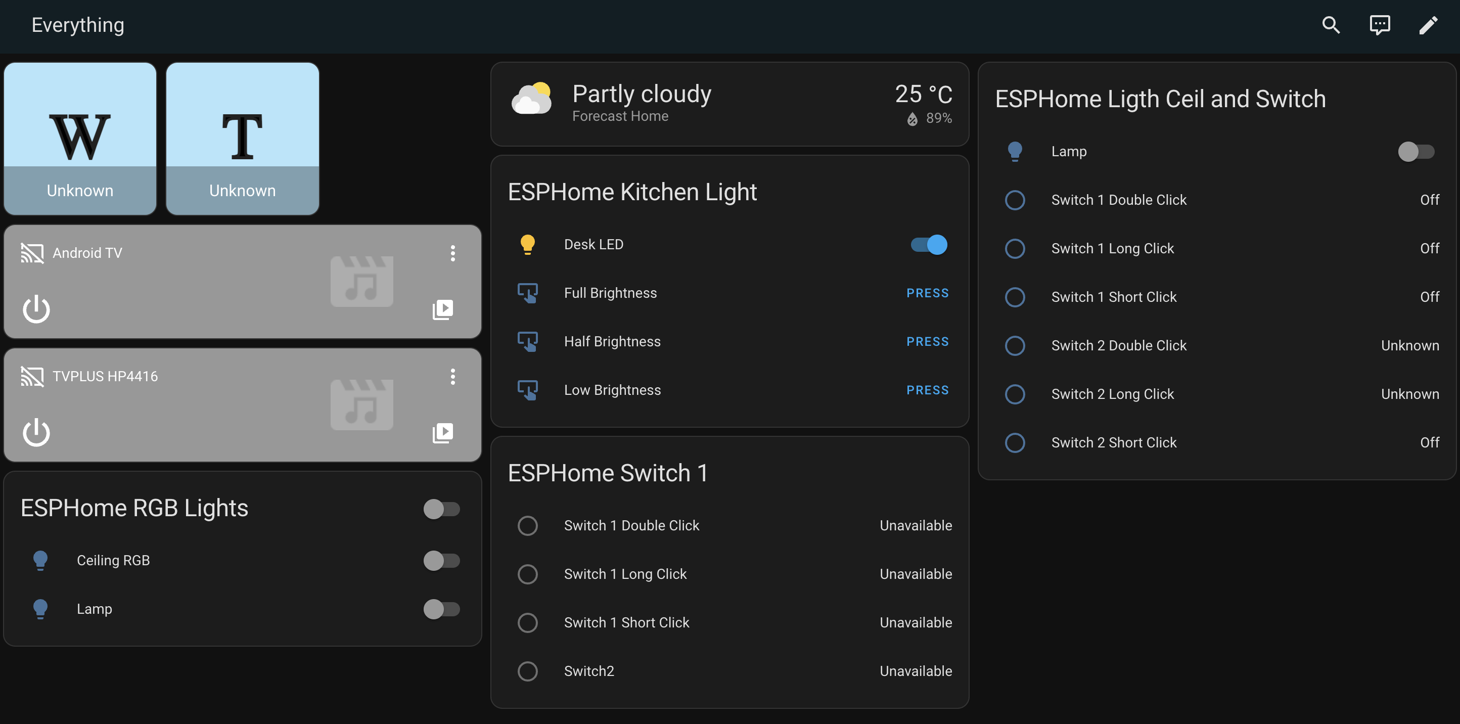
Here is how the end result of my Overview Panel in Home Assistant: